Design and Implementation of Driver for 8 DC Motors
Note: The driver for the DC motor project was done during the years 2011 – 2013 when Madi was a Master’s student.
Problem Definition
The aim of this project is to design and implement a driver for 8 DC motors to be used in a surgical robot.
L298 Driver
This IC is the most common and powerful IC to drive DC motors, Relays, and Solenoids. Each IC can drive up to 2 motors. Therefore, in order to drive 8 motors, 4 of these ICs are needed. The pins of the IC are as follows:
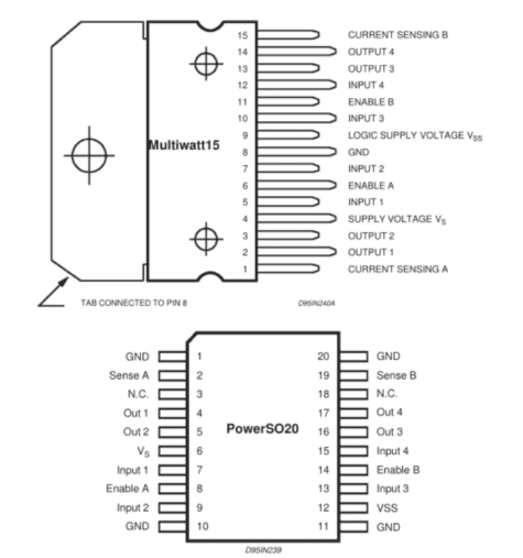
As can be seen above, the IC is presented in two packages.
This IC has 4 outputs that are connected to the motor. As mentioned before, this IC can drive two motors. Enable A, and Enable B send the PWM signal that is needed for velocity control of the DC motor.
In this project, the I/O board generated PWM signal, however, the Microcontroller can also be used to reach this goal.
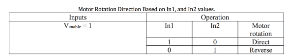
Input 1 to Input 4 pins receive 0 or 1 logic signals from the I/O board that causes the motor to rotate:
Sense A, and Sense B pins are to get feedback from the current, and in order to control the current, a resistor should be used between these pins and the ground.
Vs is the power supply for power levels that has amplifiers to provide the output current needed for the load.
Vss is the power supply for logic blocks for the IC that is equal to 5 (v). For the designed circuit, we need two supplies that it is better to use one supply and for the next one regulator should be used.
In order to filter the output, a capacitor should be used between the power supply and the ground, and based on the used motor we have chosen a 100 nF capacitor.
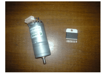
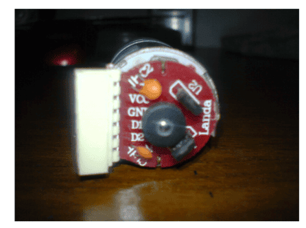
The figure below shows the motor and its driver:
Sensor on the motor
The sensor on the motor is Hall Effect Sensor. These sensors work based on the magnetic field. They have 3 pins that the digital type gives out an output of 0, or 1 pulse when in the proximity of a magnetic field.
The motor shown in the figure above has 2 hall effect sensors that generate pulses with 90-degree phase difference and can be used to differentiate between the magnetic poles on it.
Every time that the motor rotates and the magnet is in the proximity of the sensor, a pulse is generated at the output.
When the motor is rotating and a small magnet is placed on the motor, every time that the motor is rotating and the magnet is placed in front of the sensor, the sensor generates a pulse in the output.
The range of these sensors is small and in the order of millimeters. D1 and D2 pins are sensor’s output data that are filtered before sending out to the I/O board. In order to calculate the filter values, sensor output frequency should be measured, and the Nyquist theorem should be used:
Sensor’s output test
The figure below shows the sensor’s output frequency measurement test:
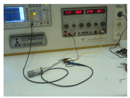
The output voltage on the Oscilloscope for V = 12 (v) is as follows:
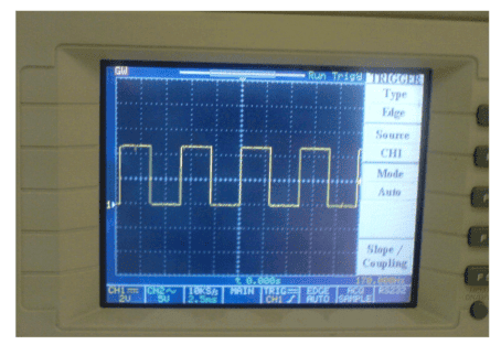
As can be seen, the output of the sensor is not noisy, so the filter is not required for now.
Designed Circuit in Altium Designer
A circuit is first tested in Proteus:
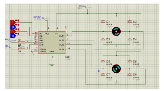
and the circuit in Altium Designer:
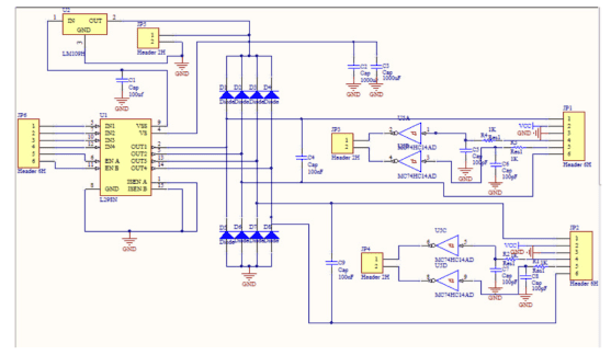
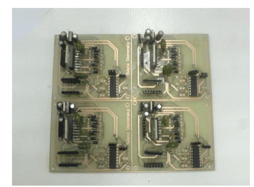
This circuit is to drive 2 DC motors, and 4 of these circuits should be used to drive 8 DC motors.
In the above circuit, JP6: Pulse input from I/O card
JP1 and JP2:
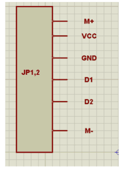
In which M+, and M- are related to one motor’s terminals. D1 and D2 are related to the sensor output. Sensor outputs are sent to the I/O card after filtering and buffering, and Jp3 and JP4 headers are for this purpose.
JP5 header is supply input to the circuit, which is equal to 12 (v), and 5(v) is supplied by the regulator.
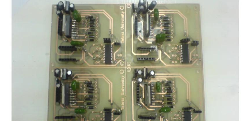
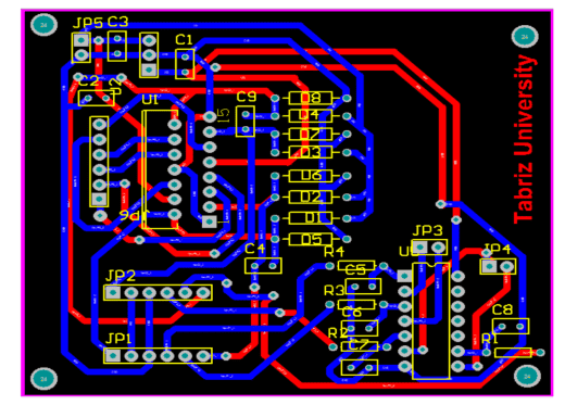
PCB designed in Altium Designer
List of Used Components
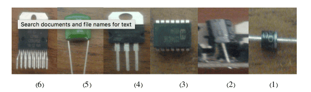
(1) 32 Diodes, (2) 12 of 100nF capacitor, (3) 4 of 74HC14 buffer, (4) 4 of 7805 voltage regulator, (5) 8 of 100nF capacitor, (6) 4 of L298 motor driver
Final Designed Circuit
Interested in re-building the circuit? Download the files below:
The designed circuit in Proteus: Click HERE!
The designed circuit in Altium Designer: Click HERE!