Fundamentals of Robot Motions: Configurations (Introduction)
This post is part one of the series of lessons on the fundamentals necessary to represent the robot’s configuration, and it gives an introduction to what we mean when we are talking about representing a robot’s configuration.
In previous lessons, we learned that the robot’s configuration answers the question of where the robot is, and we saw that there are two ways to represent the robot’s configuration: Implicit representation, where the configuration is represented by embedding the curved space in higher-dimensional Euclidean space subject to constraints and explicit representation where configuration is represented with a minimum number of coordinates. You can watch the lesson on configuration and configuration space before preceding this lesson.
We also advise reading the preliminaries lesson since the lessons are related to each other, and each one complements the other lesson.
For the full comprehension of the Fundamentals of Robot Motions and the necessary tools to represent the configurations, velocities, and forces causing the motion, please read the following lessons (note that more lessons will be added in the future):
https://www.mecharithm.com/category/fundamentals-of-robotics/fundamentals-of-robot-motions/
Robot’s Configuration on Plane
We start this lesson with a planar example to see what we mean to express the configuration of a robot. Suppose a toy car with its motion confined to the plane and two coordinate frames {s}, and {b} with their corresponding unit axes (a hat notation shows a unit vector):
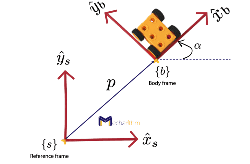
{b} is called a body frame since it is a fixed frame attached instantaneously to the moving body. Therefore, to find the configuration of the toy car, we should express the position and orientation of the body’s fixed-frame coordinates in the base frame coordinates.
One way to represent the orientation of the body coordinates in terms of the base coordinates is using a rotation matrix:
The columns of this matrix are the coordinate axes of the {b} frame expressed in the coordinate axes of the {s} frame. The dot represents the dot product between the coordinate axes, and since they are unit vectors, the dot product represents the cosine of the angle between the two vectors.
Recall that if a and b are two vectors with known length and angle between them:
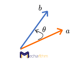
Then, the dot product of the two vectors can be expressed as the projection of one vector onto the other multiplied by the length of the other vector (in other words, it is the multiplication of the length of the two vectors and cosine of the angle between the two vectors):
The 2 by 2 rotation matrix belongs to the four-dimensional space subject to the three constraints as follows:
- Each column of the rotation matrix is a unit vector. In other words, the lengths of the column vectors are 1.
- Two columns are orthogonal to each other. In other words, the dot product of the columns is zero.
Thus, we have one degree of freedom which is parameterized by the angle α to represent the orientation. The rotation matrix is an implicit way to represent the orientation.
Now that we found a way to represent the orientation of the toy car on the plane, it’s time to represent its position. The position of the origin of the body frame in base frame coordinates can be expressed as the vector p from the origin of the {s} frame to the origin of the {b} frame:
Thus the configuration of the toy car can be represented by the pair (R,p), which is the description of the orientation and position of {b} with respect to {s}. This means that base frame {s} can be coincident with the body frame {b} by rotating the base frame coordinates around the z-axis by α and then translating the origin by p.
Robot’s Configuration in Space
Using a similar approach, we can express the configuration of a robot in space. We can use frames to represent the configuration of a robot in space. One simple way to represent the position and orientation (configuration) of a robot in space is to:
- Fix a frame to the body of the robot according to the Right-Hand Rule (RHR) (sometimes this frame is attached to an important point on the rigid body like the center of mass, but this is not required), and
- Fix a frame in space
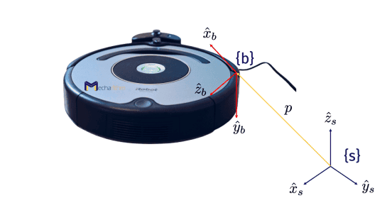
Then the robot’s configuration can be represented by the position of the origin of the body frame expressed in the space frame coordinates and the directions of the coordinate axes of the body frame expressed in the space frame coordinates. Note that the body frame is the stationary frame that coincides with the frame attached to the body at a particular instant in time.
There are several implicit and explicit representations that are used to represent the rotations and configurations in general that we will discuss in the coming lessons. In the next lesson, we will start talking about different ways to represent the orientations in robotics. The next lesson will be dedicated to Rotation matrices which are the implicit representations of orientations.
The video version of the current lesson can be watched at the link below:
References:
📘 Textbooks:
Modern Robotics: Mechanics, Planning, and Control by Frank Park and Kevin Lynch
A Mathematical Introduction to Robotic Manipulation by Murray, Lee, and Sastry
✍️ Logo design by Minro Art Group