Fundamentals of Robotics: Wrenches
In the previous lesson, we learned that screws are geometric interpretations of twists, and they can be used to express configurations in robotics. This lesson is about spatial forces or wrenches in robotics. We will talk about wrenches in this lesson, which are 6-vector representations of forces and moments in robotics. We will also become familiar with how to change the frame of representation of a wrench.
This lesson is part of the series of lessons on foundations necessary to express robot motions. For a complete comprehension of the Fundamentals of Robot Motions and the tools required to represent the configurations, velocities, and forces causing the motion, please read the following lessons (note that more lessons will be added in the future).
Also, reading some lessons from the base lessons of the Fundamentals of Robotics course are deemed invaluable.
Now let’s learn about forces and torques in robotics, which are collectively called wrenches.
A spatial force (generalized force) or a wrench is a six-vector (a vector in ℝ6) consisting of moments (torques) and forces. Therefore, a wrench consists of a linear component or pure force and an angular component or pure moment acting at a point. If f is a linear force the line of which is acting on a rigid body at a point r, and if we define a reference frame {a}, then as we saw before, the point r can be represented in the reference frame {a} as ra ∈ ℝ3 and the linear force in that reference frame can be represented as fa ∈ ℝ3.
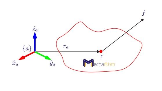
Note that the point r may be a contact point if the force is applied by one of the fingers during robotic grasping, or it will be a different point if the force is due to an external load.
You may refer to the lesson below to understand how vectors and points are represented with respect to different coordinate frame.
The linear force creates a torque or moment that can be represented as ma ∈ ℝ3 in the {a} frame and can be calculated as the cross product of the distance of the point of application of f to {a} and the force expressed in {a} frame:
Note that the point of application of the force along its line of action is immaterial.
By combining the moment and force into a single 6-vector spatial force, we get the wrench expressed in the {a} frame:
The 3-vector fa shows the magnitudes of the forces in three directions that induce a 3-vector torque or moment about the frame {a}. A wrench with a zero linear component is called a pure moment.
Let’s now see how we can change the frame of reference for a wrench.
The Relationship Between Wrench Representation in Frame {a} and Wrench Representation in Frame {b}
The values of the wrench vector depend on the coordinate frame in which the force and the moment are represented.
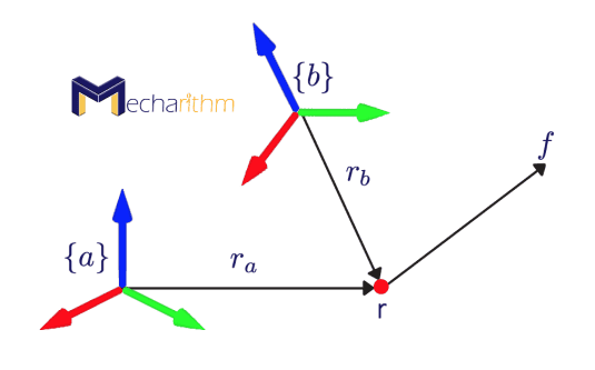
We can represent a wrench in one frame in another frame if the homogenous transformation matrix Tba is known between the frame {a} and {b}.
To learn more about homogenous transformation matrices and how to calculate them, please refer to the following lesson.
Physics tells us that power generated (or dissipated) by the (wrench, twist) pair must be the same regardless of the frame in which it is represented. Note that the dot product of a spatial force and a twist is called power and it is a coordinate independent quantity (it is the same whether the wrench and twist are represented in frame {b} or in frame {a}):
We also know from the velocities in robotics lesson that the adjoint transformation can change the frame of reference for a twist:
From the properties of matrix transpose, we can say that the transpose of the multiplication of matrics equals to the multiplication of the transpose of the second matrix and the transpose of the first matrix (AB)T = BTAT, then we can write:
Given a wrench representation in {a}, and in {b}, then the two representations are related by:
The adjoint transformation changes the coordinate frame of the wrench from the {b} frame to the {a} frame and vice versa.
Note that only the rotation matrix between the frames {a} and {b} is needed to change the coordinate frame of a moment from one reference frame to the other:
If we consider {s} to be the fixed or space frame and {b} to be the body frame then:
Now let’s see an example.
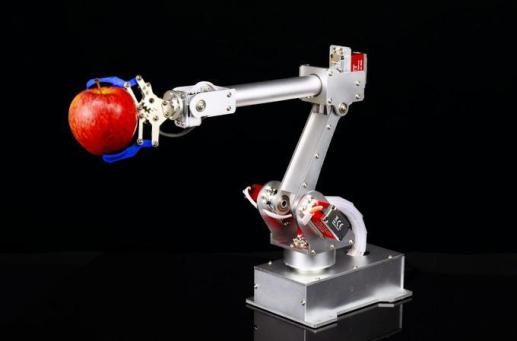
Example: Wrench Measured by the Robot Wrist’s Six-axis Force/Torque Sensor
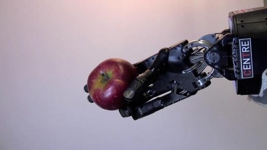
Consider, a robotic hand is holding an apple and there is a force/torque sensor on the robot’s wrist.
We know the following information:
- the mass of the apple
- direction of gravity
- location of the apple in the hand
We want to find the forces/torques measured by the sensor.
The figure below shows a schematic of the problem:
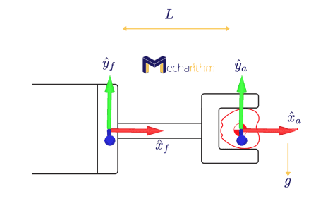
The force/torque sensor measures the forces and torques in the frame {f} and frame {a} is at the center of mass of the apple. We can write the forces and moments in frame {a} as:
Note that the moment vector is zero since the force vector passes through the origin of the {a} frame and does not produce any moment there. mg is the force due to gravity and it is in the opposite direction of the y axis. To transform this wrench to the force sensor coordinate frame, we must calculate the adjoint transformation:
The configuration of the force sensor frame {f} relative to the apple frame {a} can be calculated as:
Then, referring back to the velocities in robotics lesson, we can calculate the adjoint transformation as:
The skew-symmetric matrix representation of the position vector can be calculated by referring back to the exponential coordinates lesson as:
Then, the adjoint function can be written as the following matrix:
and finally, the representation of the wrench in the sensor coordinate frame can be represented as:
from this matrix, we can see that the wrench creates a moment of -mgL about the z-axis of the {f} frame.
Note that if more than one wrench acts on a rigid body, then the total wrench on the body is equal to the vector sum of the individual wrenches expressed in the same coordinate frame. Let’s see this with two examples.
Example: Wrench Measured by the Robot Wrist’s Six-axis Force/Torque Sensor Considering the Hand’s Weight
Suppose that a robot hand is holding an apple subject to gravity. The apple mass is m1, the gravitational field is g, and the mass of the hand is m2. What are the forces and torques measured by the six-axis force/torque sensor?
The schematic of the problem is as follows:
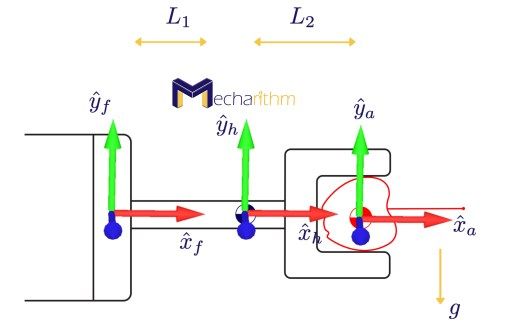
{f}, {h}, and {a} are the force/torque sensor frame, center of mass of the hand frame, and center of mass of the apple frame, respectively.
The gravitational wrench on the hand and expressed in the hand coordinate frame {h} can be expressed as the following vector:
and the gravitational wrench on the apple expressed in the apple coordinate frame {a} is:
The transformation matrices needed to calculate the adjoint transformations can be written as the following matrices:
then the wrench measured by the six-axis force-torque sensor can be calculated as the vector sum of the individual wrenches expressed in the same coordinate frame:
where the adjoint transformations can be calculated as the following matrices:
Then the wrench measured by the six-axis force/torque sensor can be expressed as the following vector:
Let’s see another example.
Example: Total Wrench in The Body Frame for Multifingered Grasping
Consider the multifingered grasping depicted in the figure below:
The goal is to determine the net effect of the forces applied at the contact points between the fingers and the object. In other words, we should map these forces to the body frame and add them as vectors.
The schematic of this problem is shown in the figure below:
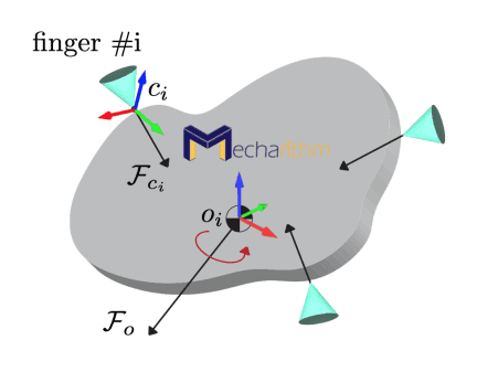
Fci is the wrench exerted by the ith finger on the grasped object represented in the {ci} frame. The net wrench on the body to determine the net effect of forces applied at the contact points between the fingers and the object, in the body coordinate frame {o} can be found by the vector sum of the individual wrenches expressed in the same coordinate frame:
Let’s see the final example.
Example: Suppose an arm-mounted mobile robot X-Terrabot is moving in a room and wants to pick up an object with body frame {e} with its end-effector with the attached frame {c}:
In the homogenous transformation matrices lesson, we calculated the configuration of the object relative to the robot’s end-effector as Tce:
Please refer to that lesson to figure out how we got this matrix. Now suppose that the weight of the block that the robot should pick up is 1 kg. This means that the robot arm should provide approximately 10 N of force in the ẑe direction (the z-direction of the block’s coordinate frame {e}) to compensate for the weight of the block. This force can be expressed as a wrench Fe in the {e} frame as:
Now we want to express this same wrench in the end-effector frame {c} as Fc. By definition that we saw in this lesson, we can write:
Tec can be calculated by inverting the transformation matrix Tce:
The transpose of the adjoint transformation can be calculated as:
Thus, the wrench in the end-effector frame {c} can be calculated as:
- The software accompanying the textbook used to create these lessons consists of functions that can return or calculate several things such as the inverse of the rotation matrix, the skew-symmetric representation of a vector and vice versa, screws, twists, etc. To download the software with documentation, please go to the link below:
Since lesson 1, we have become familiarized with the fundamentals needed to represent motion and forces in 3D space for robots and other types of mechanical systems.
We are now equipped with the tools we need to study the kinematics, statics, and dynamics for robots. In the next lesson, we will start with robot kinematics. Stay Tuned! See you in the next lesson!
References:
- Modern Robotics: Mechanics, Planning, and Control by Frank Park and Kevin Lynch
- A Mathematical Introduction to Robotic Manipulation by Murray, Lee, and Sastry
- https://www.shadowrobot.com/
- https://www.kickstarter.com/projects/1128055363/7bot-a-powerful-desktop-robot-arm-for-future-inven