Screw Motion and Exponential Coordinates of Robot Motions
This lesson is part of the series of lessons on foundations necessary to express robot motions. For the complete comprehension of the Fundamentals of Robot Motions and the tools required to represent the configurations, velocities, and forces causing the motion, please read the following lessons (note that more lessons will be added in the future):
https://www.mecharithm.com/category/fundamentals-of-robotics/fundamentals-of-robot-motions/
Also, reading some lessons from the base lessons of the Fundamentals of Robotics course are deemed invaluable.
In this lesson, we will see an introduction to screw motion in robotics, and we will also see how we can define exponential coordinates for robot motions. This is the first lesson on a series of lessons on screw theory, and more lessons will be added in the future.
Introduction to Screw Theory
Screw theory in robotics provides a foundation to express robot motions and states that any robot configuration can be achieved by starting from the home (fixed) reference frame and then integrating the constant twist (the angular velocity and the linear velocity in a compact form) over a specified time:
We will learn about twists in the next lesson but for now, remember that integrating a constant twist over time will give us the robot’s configuration.
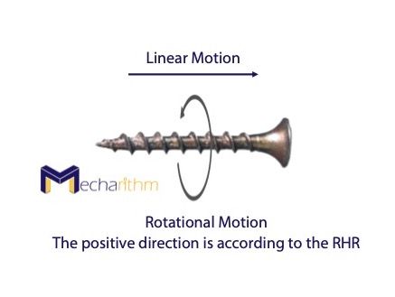
Thus, we can say that all configurations can be achieved by a screw motion (spatial rigid body displacements) that comes from the Chasles-Mozzi theorem in kinematics, which states that every displacement (rotation and translation at the same time) of the rigid body can be obtained by a finite rotation about and translation along a fixed screw axis 𝘚:
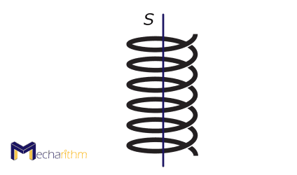
This motion is like the motion of a screw that simultaneously rotates about and translates along the same fixed axis:
First, note that using screws for describing the robot motions provides a global description of the motion that does not suffer from singularities due to using local coordinates. We discussed these singularities when we studied the three-parameter representations for orientation, such as Euler angles.
As a quick reminder, the global coordinate frame is some chosen coordinate frame with a known origin. Whereas the local coordinate frame is a frame in this global frame that the robot exists in. For instance, suppose a mobile robot is moving in a room. The global coordinate frame is somewhere in this room, usually a corner, and the local coordinate frame is on the robot itself:
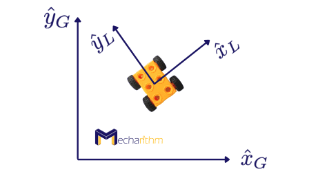
Describing the motion relative to this local coordinate frame can suffer from singularities where the mechanisms are locked and lose degrees of freedom. For instance, local representations of orientation like Euler angles and Roll-pitch-yaw angles suffer from singularities where the solution will not always exist for the inverse problem where we want to find a set of parameters for a given orientation.
On the other hand, the screw theory also provides a geometric description of robot motions that makes the kinematic analysis very simple in comparison to other methods like Denavit-Hartenberg that we will see in the coming lessons. For now, just know that the pose of the end-effector relative to the base frame (depicted in the figure below) can simply be found by the product of the exponential formula and the screw theory:
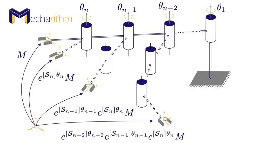
𝘚1 … 𝘚n are screw axes expressed in the fixed base frame when the robot is at its home position. θ1 … θn are joint variables, and M is the end-effector configuration when the robot is at home position. Unlike the conventional methods like Denavit-Hartenberg, this method does not require link reference frames to be defined.
Prof. Daniel Martins from the Federal University of Santa Catarina made a great presentation on the importance of screw theory for Mecharithm that puts all of this more articulately:
Exponential Coordinates of Robot Motions
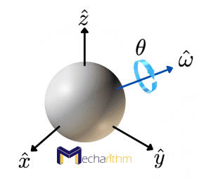
By now, we are familiar with the exponential coordinate representation for orientations, and we know that it is a three-parameter representation of orientation and parameterizes the orientation using a unit axis of rotation ῶ and the angle of rotation θ about that axis:
ῶθ ∈ ℝ3 is then the exponential coordinate representation of the orientation. We also learned about homogenous transformation matrices that are great tools to express rotations and translations in a compact 4×4 matrix:
Another possible representation of displacement (rotation and translation) is a 6-parameter representation called exponential coordinates that will be the topic of this session. The 6D exponential coordinates of a homogenous transformation T can be defined as:
Where 𝘚 is the screw axis and θ is the distance that must be traveled along the screw axis to take the frame from the initial configuration I to T.
In order for us to mathematically define the screw motion and the screw axis, we need to first study the concept of velocity in robotics, and we should become familiar with the angular velocities and the linear velocities that will be the topic of the next lesson. To conclude this lesson, let’s see some applications of screw theory that is an excellent tool for research in robotics.
Examples of Using Screw Theory in Robotics Research
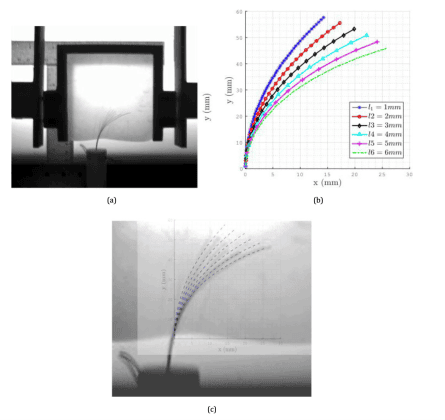
Screw theory can be used to describe the motion of continuum soft robots like steerable needles. Steerable needles are compliant needles that can be steered to a target location by rotation of the needle about its axis and translation of the needle:
The screw theory can be used to describe the motion of steerable needles in terms of an angular rotation in a plane as a function of insertion velocity and the ability to re-orient the plane in which the needle is traveling by twisting the needle at the base.
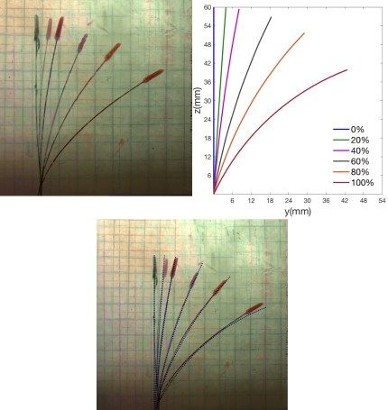
As an example, consider fracture-directed steerable needles. Fracture-directed steerable needles are a type of steerable needles in which the direction of the tissue fracture is controlled by either the tip of the needle or the waterjet, and then the steerable needle follows the path:
Screw theory can be used to describe the kinematics of these needles accurately:
The coming lessons will discuss more details about how to use the screw theory to describe motion.
That’s going to wrap up today’s lesson. We hope that it gave you a good understanding of an introduction to screw theory in robotics. In the next lessons, we will go deeper into screw theory in robotics, and we will see how we can use it to describe motion. Stay Tuned! See you in the next lesson!
The video version of the current lesson can be watched at the link below:
References:
📘 Textbooks:
Modern Robotics: Mechanics, Planning, and Control by Frank Park and Kevin Lynch
A Mathematical Introduction to Robotic Manipulation by Murray, Lee, and Sastry
📃 Articles:
- Yang, F., Babaiasl, M. and Swensen, J.P., 2019. Fracture-directed steerable needles. Journal of Medical Robotics Research, 4(01), p.1842002.
- Babaiasl, M., Yang, F., Boccelli, S. and Swensen, J.P., 2020. Fracture-directed Waterjet Needle Steering: Design, Modeling, and Path Planning. In 2020 8th IEEE RAS/EMBS International Conference for Biomedical Robotics and Biomechatronics (BioRob) (pp. 1166-1173). IEEE.