Note: Segway Robot project was done during the years 2011 – 2013 when Madi was a Master’s student.
Study on two-wheeled robots started in late 1990 in different robotic labs in different countries. The main objective is to design a balanced two-wheeled robot that has human-like abilities.
The main research challenge in these robots is the inherent instability of their dynamical system. These robots can be used as autonomous vehicles in companies, factories, or just to transport people.
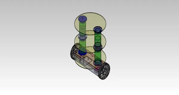
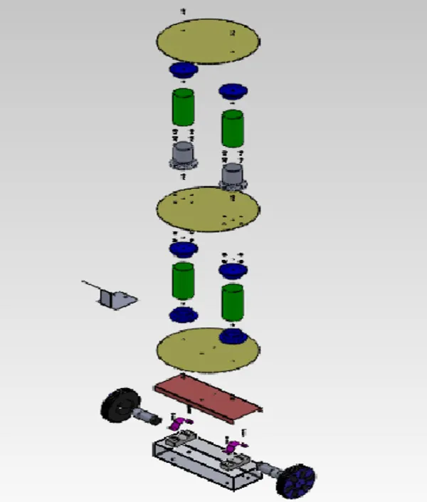
Mechanical Design of Segway Robot


Actuator Modeling

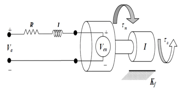
According to Kirchhoff’s law:
\[V_a – Ri – L\frac{di}{dt} – V_e = 0\]
Newton’s Law for the shaft of the motor:
\[\sum M = {\tau}_m – k_f \omega – {\tau}_a = I_R \frac{d\omega}{dt}\]
Thus:
\[\begin{bmatrix} \dot{\theta}\\ \dot{\omega} \end{bmatrix} = \begin{bmatrix} 0 & 1\\ 0 & \frac{-k_m k_e}{I_R R} \end{bmatrix} \begin{bmatrix} \theta\\ \omega \end{bmatrix} + \begin{bmatrix} 0 & 0 \\ \frac{k_m}{I_R R} & \frac{-1}{I_R} \end{bmatrix} \begin{bmatrix} V_a\\ {\tau}_a \end{bmatrix}\]
\[y = \begin{bmatrix} 1 & 0 \end{bmatrix}\begin{bmatrix} \theta\\ \omega \end{bmatrix} + \begin{bmatrix} 0 & 0 \end{bmatrix}\begin{bmatrix} V_a\\ {\tau}_a \end{bmatrix}\]
Wheel Modeling

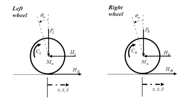
Applying Newton’s law in the x-direction and around wheel axis:
\[\sum F_x = Ma\]
\[M_w \ddot{x} = H_{fR} – H_R\]
\[\sum M_a = I \alpha\]
\[I_w \ddot{\theta} = C_R – H_{fR}r\]
Chassis Modeling

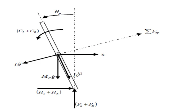
Applying Newton’s laws to the chassis’s free diagram:
\[I_p \ddot{\theta}_p – \frac{2k_mk_e}{Rr} \dot{x} + 2\frac{k_m}{R}V_a + M_p g \ell sin({\theta}_p) + M_p {\ell}^2 {\ddot{\theta}}_p = -M_p \ddot{x} \ell cos({\theta}_p)\]
\[2(M_w + \frac{I_w}{r^2})\ddot{x} = \frac{-2 k_m k_e}{R r^2} \dot{x} + \frac{2k_m}{R r} V_a – M_p \ddot{x} – M_p \ell {\ddot{\theta}}_p cos({\theta}_p) + M_p \ell \ddot{{\theta}_p}^2 sin({\theta}_p)\]
Linearizing the above nonlinear equations, the state equations of the system are as follows:
\[\begin{bmatrix} \dot{x}\\ \ddot{x}\\ \dot{\phi}\\ \ddot{\phi} \end{bmatrix} = \begin{bmatrix} 0 & 1 & 0 & 0\\ 0 & \frac{2 k_m k_e (M_p \ell r – I_p – M_p {\ell}^2)}{R r^2 \alpha} & \frac{{M_p}^2 g {\ell}^2}{\alpha} & 0\\ 0 & 0 & 0 & 1\\ 0 & \frac{2 k_m k_e (r \beta – M_p \ell)}{R r^2 \alpha} & \frac{M_p g \ell \beta}{\alpha} & 0 \end{bmatrix}\begin{bmatrix} x\\ \dot{x}\\ \phi\\ \dot{\phi} \end{bmatrix} + \begin{bmatrix} 0\\ \frac{2 k_m (-M_p \ell r + I_p + M_p {\ell}^2)}{R r \alpha}\\ 0\\ \frac{2 k_m (M_p \ell – r \beta)}{R r \alpha} \end{bmatrix} V_a\]
Segway Robot Electronics
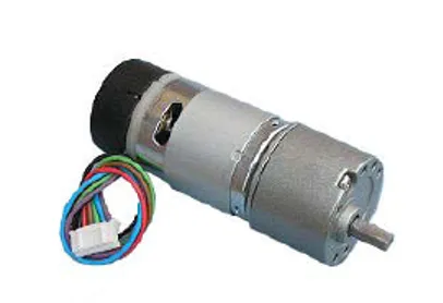
Motor specifications
EMG30, DC motor with gearbox and encoder, 170 rpm speed, 1.5 kg/cm torque. Motor driver is L298 IC.
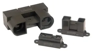
Sensor Specifications
GP2D12 distance measuring sensor, 10-80 cm range, 5(v) power supply, voltage output

Designed Segway Robot Circuit in Proteus
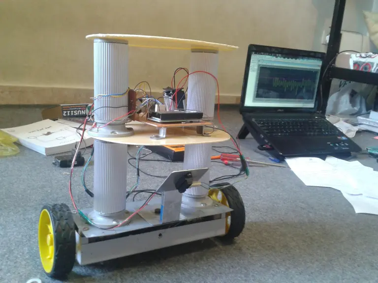
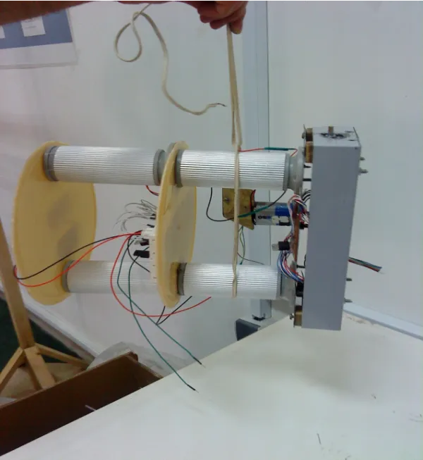
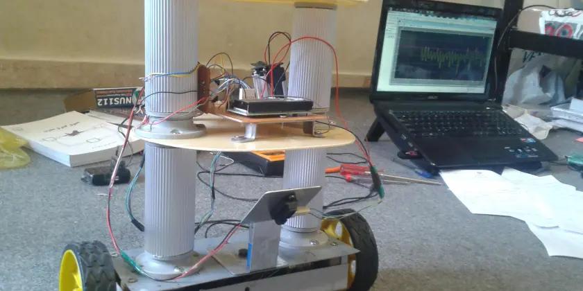
Built Segway Robot


If you enjoyed this post, please consider contributing to help us with our mission to make robotics and mechatronics available for everyone. We deeply thank you for your generous contribution!
Do not forget to contact us:
Be sure to let us know your thoughts and questions about this post, as well as the other posts on the website. You can either contact us through the βContactβ tab on the website or email us at support[at]mecharithm.com.
Send us your work/ research on Robotics and Mechatronics to have a chance to get featured in Mecharithm’s Robotics News/ Learning.
Follow Mecharithm in the following social media too: