Task Space and Workspace for Robots
In this post, you will learn about the task space and workspace for robots and understand their difference with the robot’s C-space. You can find a comprehensive post about the C-space of the robot HERE.
⚠️ This post also has a video version that complements the reading. Our suggestion is to watch the video and then read the reading for a deeper understanding.
We saw before that the robot’s C-space is the space of all possible configurations of a robot. But what does task space and workspace mean for robots? If you want to learn about task space and workspace, please keep reading.
The Task Space of a Robot
By definition, the robot’s task space is the space in which the robot’s task is naturally expressed. We should only know about the task and not the robot to find the task space, and it is possible that the robot cannot reach some configurations.
Example: If the task is to control the position of the tip of a marker on the board, then the task space is the Euclidean plane:

Example: If the task is to control a rigid body’s position and orientation, then the task space is the 6D space of rigid body configurations. You can read about this HERE!
The decision of how to define the task space is driven by the task independently of the robot. For instance, a pick and place task may require only 3 DOFs while the robot arm has 6 DOFs.
The Workspace of a Robot
By definition, the workspace of a robot is a specification of the reachable configurations of the end-effector. The workspace of a robot has nothing to do with a particular task.
Example: Suppose a planar robot arm below where the lengths of two links are not equal:
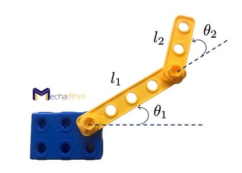
The robot arm has two revolute joints, and the lengths of the links are as follows:
The workspace of this robot, if we do not impose any limitations on the joint angles (both angles can be freely changed from 0 to 360o), can be visualized like the figure below:
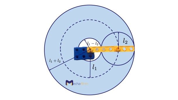
The circle with a radius of l1 – l2 is the area that the robot end-effector cannot reach.
If the lengths of the two links are equal, that is l1 = l2 then the robot’s workspace can be visualized as follows:
Note: The workspace is the reachable configurations of the end-effector of the robot.
If we put constraints on the joint angles as:
Then the workspace of the 2R planar robot with limitations on the joint angles will be as the following figure:
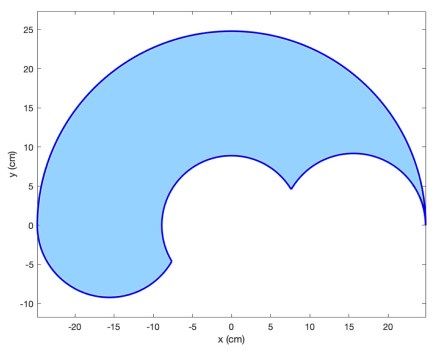
The shaded area shows the space that the end-effector of the robot can reach.
If you would like to re-create the above results or experiment with various joint limitations, try the MATLAB code below that visualizes the workspace of the 2R planar robot arm:
% This code can plot the workspace of a 2R planar robot
% this code is written by Madi Babaiasl

% number of samples
N = 1000;

% link lengths
l1 = 15.6;
l2 = 9.2;

% joint angle limitations
theta1_min = 0;
theta1_max = 180;
theta2_min = 0;
theta2_max = 150;

% limitations on theta1
theta1_start_end = [theta1_min,theta1_max];

% change the angle to Radians
theta1_start_end = theta1_start_end*pi/180;

% limitations on theta2
theta2_start_end =[theta2_min,theta2_max];

% change the angle to Radians
theta2_start_end = theta2_start_end*pi/180;

% joint angles
theta1 = linspace(theta1_min,theta1_max,N);

% change the angle to Radians
theta1 = theta1*pi/180;
theta2 = linspace(theta2_min,theta2_max,N);

% change the angle to Radians
theta2 = theta2*pi/180;

%intialization of the x and y
x = zeros(2*length(theta1_start_end),length(theta2));
y = zeros(2*length(theta1_start_end),length(theta2));

% x and y are calculated using kinematics
for i = 1:2
    for j = 1:length(theta1)
        x(i,j) = l1*cos(theta1(j)) + l2*cos(theta1(j) + theta2_start_end(i));
        y(i,j) = l1*sin(theta1(j)) + l2*sin(theta1(j) + theta2_start_end(i));
    end
    for k = 1:length(theta1)
         x(i+2,k) = l1*cos(theta1_start_end(i)) + l2*cos(theta1_start_end(i) + theta2(k));
         y(i+2,k) = l1*sin(theta1_start_end(i)) + l2*sin(theta1_start_end(i) + theta2(k));
    end
end

x = x';
y = y';

%plotting
plot(x(:,1),y(:,1),'b','LineWidth',2)
hold on
plot(x(:,2),y(:,2),'b','LineWidth',2)
plot(x(:,3),y(:,3),'b','LineWidth',2)
plot(x(:,4),y(:,4),'b','LineWidth',2)

xlabel('x (cm)')
ylabel('y (cm)')
axis equal
The C-space, Workspace, and Task Space for a 3R Spherical Robot Wrist
Consider the spherical robot wrist with three revolute joints (3 DOFs) as pictured below:
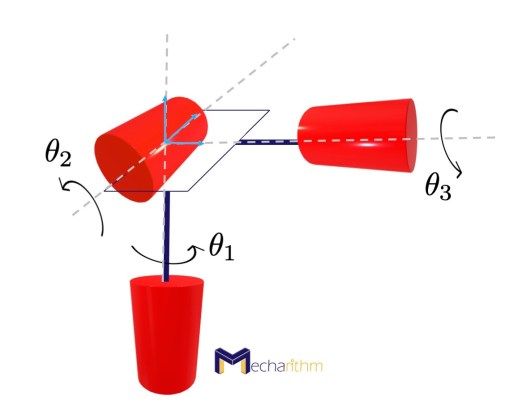
The three axes of rotation of the three revolute joints are orthogonal to each other and intersect at a point.
The spherical wrist is also called a 3R orienting mechanism since the coordinate frame can achieve any orientation by rotating the joints.
In the video below, you can see Denso’s 6 DOF robot arm with spherical wrist with 3 DOFs. Look closely at the wrist’s motion and try to identify the three rotations of the wrist joint.
Because it has three revolute joints, the 3D C-space can be expressed as follows:
The Workspace may be defined as the 3D space of orientations of the frame:
The Task space depends on the task. For example, if we define the task to be pointing a laser pointer, then rotations about the axis of the laser are not necessary, and the task space can be defined as the set of directions that the laser can point:
The C-space, Workspace, and Task Space for the SCARA Robot
Consider the SCARA robot shown in the figure below:
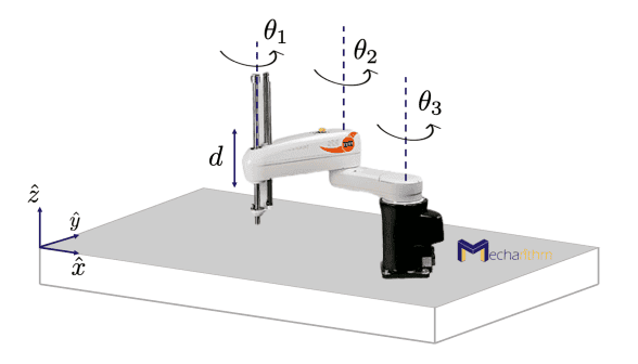
The SCARA robot is an open-chain RRRP robot with three rotational and one translational degrees of freedom. The end-effector configuration can be described by four parameters determining the Cartesian position of the end-effector and the orientation of the end-effector in the x-y plane:
The SCARA robot is usually used for table-top pick-and-place tasks. You can watch a short video from FANUC America Corporation here!
The Task space can then be defined as follows for pick-and-place tasks:
The Workspace is the reachable points in (x,y,z) Cartesian space since all orientations can be achieved at all reachable points:
The Dexterous Workspace vs. the Reachable Workspace
The workspace concept defined above is the reachable workspace of the robot that are the configurations that the robot end-effector can reach.
There is another workspace concept known as the dexterous workspace. By definition, the dexterous workspace is the set of all positions that can be reached with all possible orientations. Let’s see these two concepts with an example:
Think about the farthest points that you can reach with your fingertips. Those points are the outer boundary of your reachable workspace (points you can reach with at least one orientation). However, the dexterous workspace is a subset of the reachable workspace that are points that you can reach while you are able to move your joints as usual (you can reach those points with all orientations).
Important Notes about the Task space and the Workspace
- The task space and the workspace relate to configurations of the end-effector of a robot and not to the entire robot’s configuration.
- The user can decide that some freedoms of the end-effector (for example, its orientation) do not need to be represented for the task space and workspace.
- A point in the task space or the workspace can be reached by more than one robot configuration.
- Some points on the Task space may not be reachable at all by the robot.
- All points in the Workspace are reachable by at least one configuration of the robot.
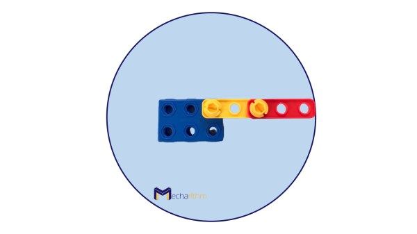
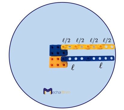
- Two mechanisms with different C-spaces may have the same workspace. For example, a planar 2R open-chain robot with link lengths of ell has the same workspace as a planar 4R open-chain robot with link lengths of ell/2:
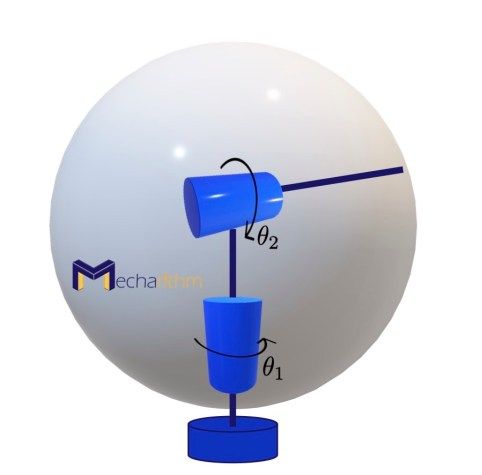
- Two mechanisms with the same C-spaces can have different workspaces:
For example, the configuration space of a 2R planar open-chain robot and a 2R open-chain spherical robot is the 2D surface of a torus:
but the workspace of a planar 2R open-chain robot is a planar disk, as we saw above, and the workspace of a spherical 2R open-chain robot is the surface of a sphere:
You can also watch the whole lesson in the video below:
References:
Textbooks:
- Modern Robotics: Mechanics, Planning, and Control by Frank Park and Kevin Lynch
- A Mathematical Introduction to Robotic Manipulation by Murray, Lee, and Sastry
Videos: