Unit Quaternions to Express Orientations in Robotics
In the lesson about the Exponential Coordinate Representation of the orientation, we saw that the logarithm could be numerically sensitive to small rotation angles θ because of the division by sinθ. We also saw that all other three-parameter representations of SO(3), like Euler angles and roll-pitch-yaw angles, suffer from similar singularities in representation, and this means that the solution will not always exist for the inverse problem where we want to find a set of parameters for a given orientation. Therefore, an alternative representation of the orientation named Unit Quaternion is used that alleviates the singularity at the cost of having the fourth variable in the representation.
This lesson is part of the series of lessons on foundations necessary to express robot motions. For the full comprehension of the Fundamentals of Robot Motions and the necessary tools to represent the configurations, velocities, and forces causing the motion, please read the following lessons (note that more lessons will be added in the future):
https://www.mecharithm.com/category/fundamentals-of-robotics/fundamentals-of-robot-motions/
Also, reading some lessons from the base lessons of the Fundamentals of Robotics course are deemed invaluable.
Definition of Unit Quaternions to Express Orientations in Robotics
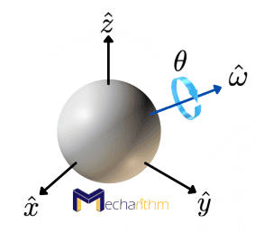
As we saw in the lesson on the Exponential Coordinates for Rotation, every rotation matrix R ∈ SO(3) has an exponential coordinate representation ῶθ such that
As we also saw before, we can visualize the exponential coordinates for the spherical space of orientations, SO(3), as the following figure:
Then, the unit quaternion representation of R is defined as the four-vector q ∈ ℝ4
It is clear from the definition that q is a unit vector ||q|| = 1, and therefore we only have three degrees of freedom in choosing the four coordinates of q. Geometrically q is a point on the 3D unit sphere in ℝ4, and therefore it can also be identified with a 3-sphere S3. As a side note, a 3-sphere is a higher-dimensional form of the sphere that we know and can be embedded in four-dimensional Euclidean space as the set of points equidistant from a fixed central point. The video below shows the 2-sphere, which is a 2D sphere that we can embed in 3D Euclidean space subject to one constraint, and the 3-sphere, which is a 3D sphere that we can embed in 4D Euclidean space subject to one constraint:
Finding a Unit Quaternion Expressing a Given Orientation in Robotics
Now let’s solve the problem of finding a unit quaternion that expresses a given orientation. Suppose that an orientation is represented by a rotation matrix R expressed by its individual entries as
From the definition of the unit quaternions, we saw that q0 = cos(θ/2), so we first should find an expression for cos(θ/2) in terms of the elements of the rotation matrix R.
In the lesson about the exponential coordinates of orientation, we saw that the trace of the rotation matrix R has the following relationship to the rotation angle θ:
And from trigonometry, it’s easy to find an expression for cosθ in terms of cos(θ/2) as
Therefore, the expression for cos(θ/2) can be found as:
Because we define 0≤θ≤π and thus 0≤θ/2≤π/2 then, θ/2 is in the first quadrant, and cos(θ/2) is positive. Therefore:
Now, let’s find the other three coordinates of the unit quaternion q1,q2, and q3. From the definition, we have
And, from the lesson about the Exponential Coordinates of Rotation, we know that
From trigonometry, we can write
Therefore the expressions for other coordinates of the unit quaternion can be found as:
Therefore, the elements of the unit quaternion q can be obtained directly from the entries of the rotation matrix R.
It’s worth stopping here and thinking about the unit quaternions representing the rotation operators of the unit axes. From the lesson about the rotation matrices, we saw that the rotation operators about the three unit axes could be expressed by the following rotation matrices:
Therefore, we can calculate the unit quaternion representation of rotations about unit axes using the approach that we discussed here. By simple calculations, we can derive that cos(γ∕2) + i sin(γ∕2), cos(β∕2) + j sin(β∕2), and cos(α∕2) + k sin(α∕2) are the unit quaternion representations of the rotations about the unit axes x, y, and z, by γ, β, and α, respectively. The equations are derived using the approaches discussed here and considering that a unit quaternion has one real coordinate and three imaginary coordinates. Formally, if q is a unit quaternion q ∈ S3 then q can be defined in terms of its real and imaginary coordinates as
Where i, j, and k are imaginary units that have the following properties (Hamilton, who first invented quaternions, made these rules):
These rules make quaternions non-commutative under multiplication. The simulation below shows example quaternions that represent rotations about the unit axes by 90o:
With the expressions that we found for the quaternions expressing the rotations about the unit axes, we can see the physical interpretations for the unit quaternions 1, i, j, and k. 1 represents the identity rotation R = I (R = I was the singularity of the axis-angle representation but not anymore for the quaternion), and i, j, and k represent rotations about the unit axes x, y, and z by 180o, respectively:
We also know that both q ∈ S3 and its antipodal point -q ∈ S3 produce the same rotation, so, for instance, both 1 and -1 represent the identity rotation R = I.
Converting Euler Angles to Unit Quaternions
The drill to convert the Euler angles to the corresponding Quaternion is as in previous lessons when we were given one representation and asked to convert it to another representation. The approach is, we should first find the desired orientation that the first set of coordinates gives us and then solve the required parameters from the second representation to achieve the desired orientation.
As the specific case of Euler Angles to Quaternions, let’s suppose we have a set of ZYZ Euler angles as (α,β,γ) and we want to find the quaternion coordinates (q0,q1,q2,q3) such that we get the same orientation given by ZYZ Euler angles. You know the drill, first find the desired orientation using the given Euler angles as (refer to the lesson on Euler angles for this equation):
Then, when we have the desired orientation, we’ll use the approach discussed above to find the set of quaternions representing the same orientation.
Example: Converting a set of Euler Angles to Unit Quaternions
We want to find the set of quaternions that give the same orientation provided by the set of ZYZ Euler angles (30o,60o,45o).
Using the approach that we discussed, the rotation matrix from the set of ZYZ Euler angles can be found as
Therefore, the set of quaternions giving the same orientation can be calculated as
For your convenience, you can use the following function written in MATLAB to calculate the same result:
function [q0,q1,q2,q3] = euler2quaternion(a,b,g)
    % this function converts euler angles to quaternions
    % This function is written by Dr. Madi Babaiasl
    % The code is not optimized for efficiency nor robustness
    % the code also does not do full error-checking on its inputs
    % It is meerly for educational purposes

    % convert angles in degrees to radians
    a = a*pi/180;
    b = b*pi/180;
    g = g*pi/180;

    % rotation matrix from Euler angles
    % desired orientation
    R_d = [cos(a)*cos(b)*cos(g)-sin(a)*sin(g) -cos(a)*cos(b)*sin(g)-sin(a)*cos(g) cos(a)*sin(b);...
           sin(a)*cos(b)*cos(g)+cos(a)*sin(g) -sin(a)*cos(b)*sin(g)+cos(a)*cos(g) sin(a)*sin(b);...
           -sin(b)*cos(g) sin(b)*sin(g) cos(b)];

    %set of quaternions giving the same orientation expressed by Euler angles
    q0 = 0.5*sqrt(1+ R_d(1,1) + R_d(2,2) + R_d(3,3));
    q1 = (1/(4*q0))*(R_d(3,2)-R_d(2,3));
    q2 = (1/(4*q0))*(R_d(1,3)-R_d(3,1));
    q3 = (1/(4*q0))*(R_d(2,1)-R_d(1,2));
end
Now let’s see a simulation to see that both ZYZ Euler angles and the Unit Quaternion will give the same orientation:
Finding a Rotation Matrix R Representing a Given Orientation Expressed by a Unit Quaternion q
Suppose that an orientation in robotics is given by a unit quaternion (q0,q1,q2,q3), then the corresponding rotation matrix R can be obtained by a rotation about the unit axis in the direction of (q1,q2,q3) by an angle 2cos-1q0. Using the Rodrigues’s Formula that we learned in the lesson about the Exponential Coordinate Representation of the Orientation, and some lengthy math, the rotation matrix R can be expressed in terms of the unit quaternion coordinates as
It is evident from the expression for R that both q ∈ S3 and its antipodal point -q ∈ S3 produce the same rotation matrix R, and therefore, for every rotation matrix, there exist two unit quaternion representations that are antipodal to each other.
Example: Converting a Unit Quaternion to Its Equivalent Exponential Coordinates
We want to find the unit axis of rotation and the angle about this unit axis that can be represented by the unit quaternion defined as
Solution:
This quaternion is indeed a unit quaternion and can represent an orientation since
The reason that the quaternion should be a unit quaternion to represent an orientation is that if it is not, then the matrix representing that quaternion will lack the qualities of a rotation matrix that we discussed in the lesson on rotation matrices.
Now that we ensured that the quaternion is indeed a unit quaternion and can represent a rotation let’s find the axis-angle representation. For this, we will construct the rotation matrix representing this quaternion using the equation above, and we get
With this rotation matrix, we can use the matrix logarithm of rotations that we learned in the Exponential Coordinates Representation of Orientation lesson and calculate the axis and angle as follows
Thus, the above unit quaternion represents a rotation about the unit axis ῶ = (1,0,0) by an angle of 90 degrees. See the simulation below that shows that both the quaternion and axis angle give the same orientation:
Product of Two Rotations Expressed with Unit Quaternions
Suppose that two orientations in 3D are expressed using two unit quaternions ±q ∈ S3 and ±p ∈ S3, and we want to find the unit quaternion representation for the multiplication of q and p.
We know that a unit quaternion consists of a real part and three imaginary parts. Thus q and p can be defined in terms of their real and imaginary parts as
Therefore the multiplication of two rotations expressed by unit quaternions can be expressed as another quaternion as
Note that in order to find this expression, we used the laws of quaternion multiplication set by Hamilton discussed in this lesson.
Demonstration: Unit Quaternion Representation of the Orientation of the UR5e Robot’s Tool Relative to the Base Frame
Suppose the six degrees of freedom UR5e robot is in its home position with the reference frames attached to the tool and robot’s base as the figure below:
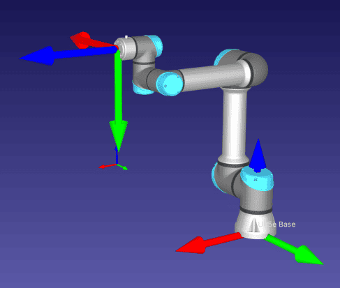
In this configuration, the orientation of the tool frame relative to the base frame can easily be found as the rotation matrix below:
Therefore in this configuration, the unit quaternion representation of the tool frame relative to the base frame can be calculated as
So, the unit quaternion representation of the orientation is q = 0.5 – 0.5i + 0.5j -0.5k.
Demonstration: enDAQ Sensors with IMU Units Can Output Orientations in Quaternions
enDAQ makes sensors that have IMU units and can output orientations in quaternions. The figure below shows an example sensor with such ability:

For instance, in the video below, the orientation starts from the (1,0,0,0) quaternion that features the identity orientation, then as the user rotates the sensor about the x,y, and z-axes, the corresponding quaternions change.
Other Applications for Unit Quaternions
Unit quaternions are not only fascinating to roboticists, but they also have other applications. For instance, Tomb Raider (1996) is the first computer game that was developed using quaternions to achieve smooth 3D rotation. For instance, the video below shows a comparison between the old animation exporter and the new one, which supports quaternion rotations:
That’s going to wrap up today’s lesson. We hope that it gave you a good understanding of unit quaternions and how they are used to express orientations. We will continue with the orientation in the next lesson and learn about Cayley-Rodrigues Parameters to Express Orientations in Robotics.
The video version of the current lesson can be watched at the link below:
References:
📘 Textbooks:
Modern Robotics: Mechanics, Planning, and Control by Frank Park and Kevin Lynch
A Mathematical Introduction to Robotic Manipulation by Murray, Lee, and Sastry
📹 Videos:
🌐 Websites: